

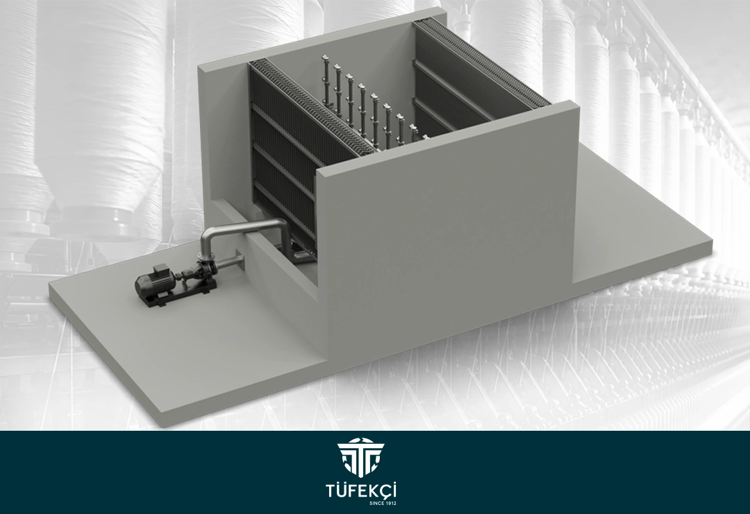
Climate control products are the components that sit inside a central air conditioning plant and prepare the air before it ever reaches the production hall. In a textile facility, that preparation happens in a fixed order: return air is filtered, moved by fans, directed through dampers, brought to the right temperature by coils, and finally corrected for humidity. Remove any one stage and the rest lose their accuracy.
Tüfekçi Makine manufactures five product groups for this stage of the system: rotary filters, axial fans, aluminum air dampers, heating and cooling coils and humidification units. Each one is produced as part of our construction-type power plant systems, meaning the units are built to the dimensions and air volumes of the specific building rather than pulled from a fixed catalog size.
The pages below explain what each product does, where it belongs in the air path, and which conditions make one configuration more suitable than another. If you already know the capacity you need, the quotation request form is the fastest route to a technical offer.
Why Air Conditioning Is a Production Parameter, Not a Comfort Item
Cotton, viscose and blended fibers respond to their surroundings. At low relative humidity, fibers lose flexibility, static electricity builds up on machine surfaces, and yarn breakages climb. At excessive humidity, the material becomes sticky and running speeds have to be reduced. Neither situation shows up on a maintenance report, but both show up in the daily production figure.
Temperature works the same way. A ring spinning hall that drifts a few degrees above target over the course of a shift changes the moisture holding capacity of the air, which in turn changes the effective humidity around the machine even if the humidification unit output stays constant. This is why temperature and humidity are always managed together rather than as separate systems.
Dust adds the third variable. Fiber fly circulating in return air settles on machinery, blocks coil surfaces and reduces the airflow the fans were sized for. Filtration is therefore not only an air quality measure but a way of protecting the performance of everything downstream of it. Our textile air conditioning solutions treat these three variables as a single design problem.
Rotary Filter: Continuous Cleaning Without Stopping the Line
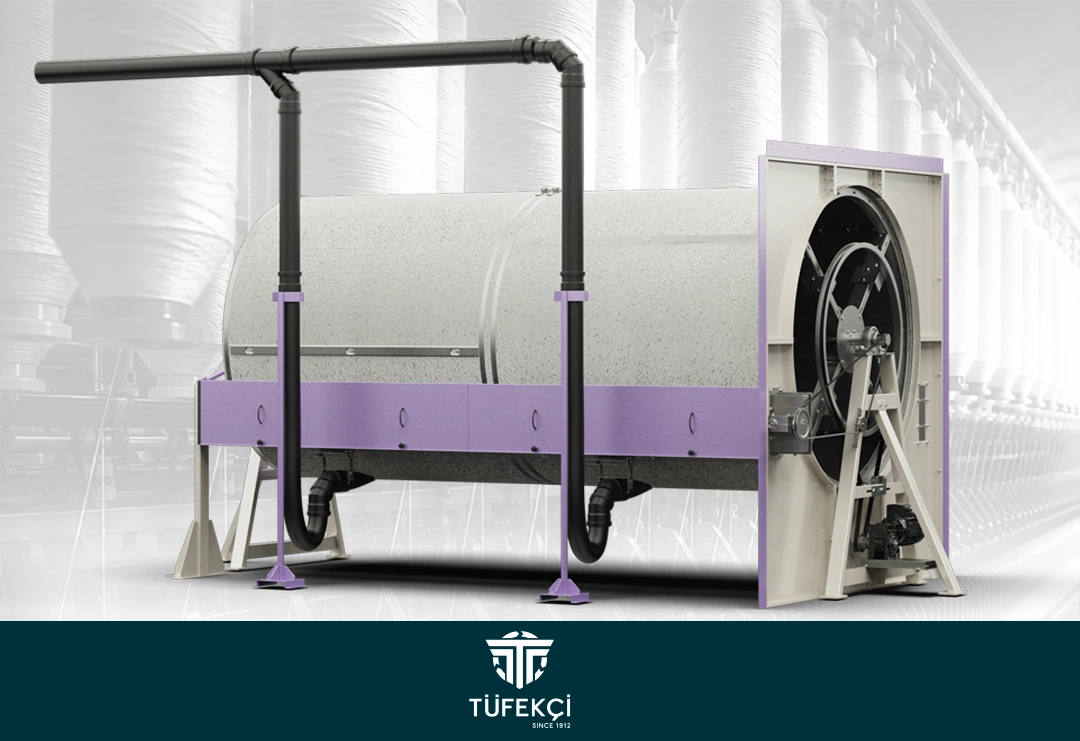
The rotary filter is the first station most return air passes through. Its rotating drum surface captures dust and fiber, while an automatic cleaning mechanism removes the collected material as the drum turns. Because cleaning happens during operation, filtration pressure loss stays within a narrow band instead of climbing between manual cleaning intervals.
That stability matters more than raw efficiency figures. A filter that clogs progressively forces the fan to work against rising resistance, which raises energy draw and slowly reduces the air volume delivered to the hall. Keeping the surface clean keeps the whole plant operating at its design point.
The body is built for continuous industrial duty, and maintenance requirements stay minimal thanks to the self cleaning action. In facilities with heavy dust loads, the rotary filter usually works alongside equipment from our dust and lint collection solutions, so that captured waste is transported and compacted rather than accumulating inside the plant room.
Axial Fan: High Air Volume Where Resistance Is Low
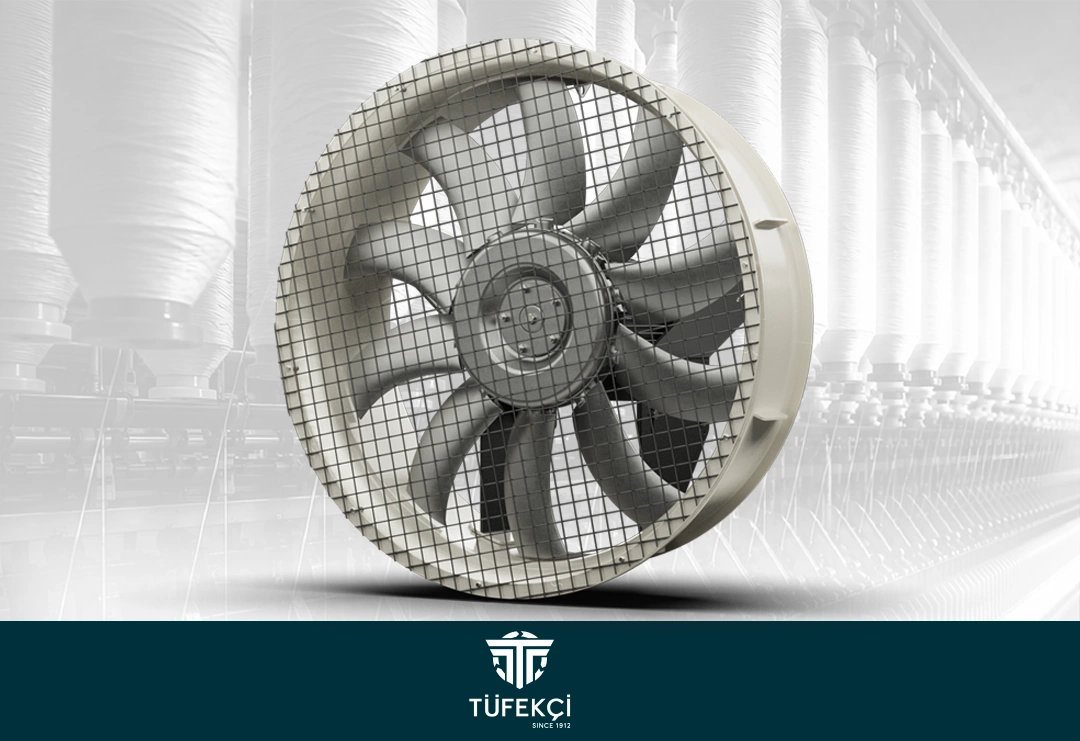
Ask any plant engineer which component defines the character of an air conditioning system and the answer is usually the fan. Axial fans move air parallel to the shaft, which makes them the right choice when the priority is shifting large volumes against relatively low static pressure. Supply and exhaust duties in textile air conditioning plants fall squarely into that category.
Blade angle, motor selection and casing dimensions are matched to the calculated air volume of the building. Oversizing wastes energy for the life of the installation, while undersizing means the system never reaches its design conditions no matter how well the coils and humidifiers perform. Sizing is therefore done from the actual duct layout, not from an approximate room volume.
Balanced impellers and correct bearing selection keep vibration and noise within acceptable limits, which also extends service intervals. When the fan runs on a frequency converter through our electrical and automation solutions, airflow can be adjusted to the load of each shift instead of running at full speed continuously.
Aluminum Air Damper: Directing the Air the Plant Has Already Conditioned
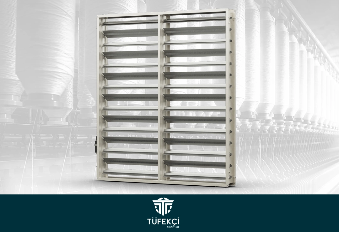
A damper looks like a simple part until you consider what it controls. Fresh air, return air and exhaust air all share the same plant, and the ratio between them decides how much energy the system spends and how quickly indoor conditions recover. The damper sets that ratio.
Aluminum construction keeps the blades light enough for responsive movement while resisting the moisture that is always present in a humidified air stream. Blades are linked so that they open and close together, and the frame is manufactured to duct dimensions to limit leakage in the closed position.
Dampers can be operated manually or through actuators tied into the control system. In automated plants, the position signal is read and adjusted continuously, which allows free cooling in mild weather and full recirculation when outdoor conditions would otherwise work against the setpoint. Sensor groups placed in the ducts provide the reference values for those decisions.
Heating and Cooling Coil: Bringing Air to the Target Temperature
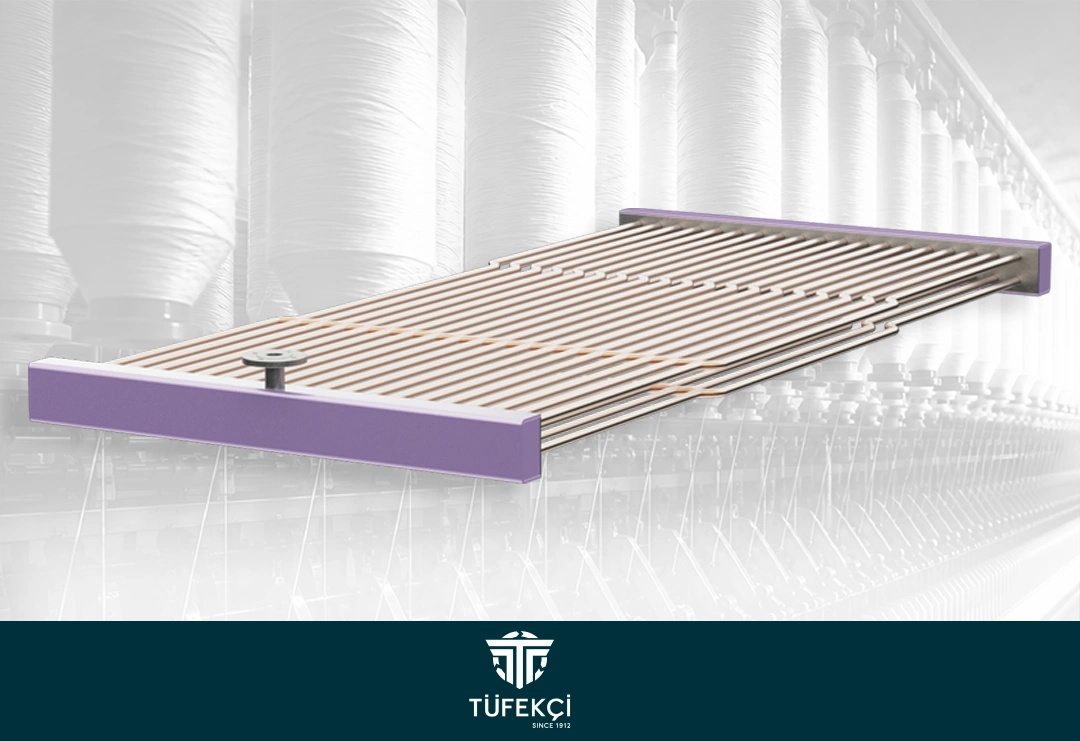
Coils carry hot or chilled water through finned tubes, and the passing air gives up or takes on heat across that surface. The design variables are tube arrangement, fin spacing and face area, and each one is a trade-off between thermal capacity and air side resistance.
Fin spacing deserves particular attention in textile plants. Fins packed too closely give excellent heat transfer on paper but trap fiber quickly, and a blocked coil is both a thermal problem and an airflow problem. Spacing is selected with the expected dust load in mind rather than pushed to the theoretical maximum.
Material choice follows the water quality and the operating environment. Copper tube with aluminum fins is the standard combination, with alternatives available where the circuit or the atmosphere requires them. Headers, connections and drain pans are sized so that condensate leaves the unit cleanly during cooling operation.
Humidification Units: Holding Relative Humidity Where the Fiber Needs It
Humidification units maintain the correct moisture level in the production area, stabilize fiber behavior and reduce static electricity buildup. Controlled distribution across the hall is what makes the difference, since a well controlled average value means little if one end of the building sits ten points below the other.
The units use spraying or evaporation technology depending on the water quality, capacity and control precision required. Both approaches are built for continuous operation, and both are adjusted through control panels that hold the setpoint within a defined tolerance rather than switching between extremes.
Alongside the direct effect on yarn quality, correct humidity reduces airborne dust because fibers are less inclined to separate and float. That reduces the load on the filtration side of the plant, which is one of the clearest examples of how these components support each other.
How the Five Products Work Together in One Plant
Reading each product in isolation gives an incomplete picture, so it helps to follow the air through a full cycle. Air leaves the production hall carrying heat, moisture and fiber, and returns to the plant room where it is corrected stage by stage before being supplied back.
The sequence in a typical construction-type installation runs as follows:
- Return air enters the plant and passes through the rotary filter, where dust and fiber are separated and removed continuously.
- Dampers set the mixing ratio between filtered return air and fresh outdoor air according to the season and the current load.
- The heating or cooling coil brings the mixed air to the required temperature before any moisture is added.
- The humidification unit raises relative humidity to the setpoint and distributes it evenly across the air stream.
- The axial fan delivers the conditioned air back to the hall through the duct network at the designed volume and pressure.
Control panels and SCADA systems supervise the whole loop, recording conditions and adjusting fan speed, damper position, valve opening and humidifier output without operator intervention.
Selecting the Right Configuration for Your Facility
No two textile plants have the same requirements, and the correct specification depends on details that only appear during a site assessment. Building volume, machine heat load, process type and local climate all shift the answer.
The following points usually determine the final configuration:
- Process type: ring spinning, open end, weaving and knitting halls each have their own temperature and humidity targets.
- Dust load: heavier fiber fly calls for wider fin spacing and closer coordination with waste collection equipment.
- Available plant room space: where floor area is limited, a packaged air handling unit may suit better than a built-in plant.
- Water quality and supply: this influences both humidifier technology and coil material selection.
- Automation level: manual, panel controlled and fully automated systems differ in cost and in day-to-day consistency.
In short, the five climate control product groups form one continuous chain, and the value of each depends on how well it is matched to the others. Our engineering team sizes them together based on your building and process data. For an assessment of an existing installation, use the service request form, and for replacement components on running systems, the spare parts request page reaches the right department directly. You can also review the full range on our products page or get in touch to discuss a project.
